Real-Time Profiling
Beam intensity profiling is an essential tool in many aspects of photonics. The precise intensity distribution in a focused laser beam is critical in many applications: flow cytometry, laser printing, medical lasers, and cutting lasers are just a few examples. Intensity profile measurements can characterize and improve a product or process, leading to substantial cost and time savings that can pay for the measurement instrument many times over. If you have ever used a conventional XY single plane profiler to measure and adjust a focused beam, then you know how time consuming the procedure can be. Measure once, move the profiler along the z axis, measure in a second plane, estimate the focus position, readjust in z, measure again … often a long, tedious, and convoluted process. This white paper describes how the unique, patented, real-time multiple z-plane XYZΘΦ capabilities of the BeamMap2 slit-scan profiler can speed and simplify laser assembly alignment.
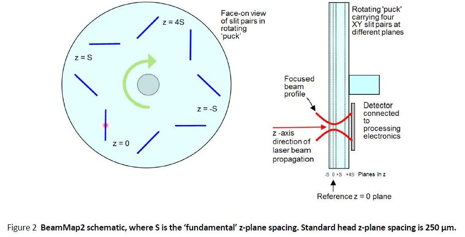
BeamMap™2 Multi-plane Slit Scan Beam Profiling
Standard slit scanners translate an XY slit pair in a single plane between the beam and a single element detector. The USB 2.0 port-powered BeamMap2, with XY slit pairs in multiple Z planes on a rotating 'puck', measures multiple Z plane XY profiles and calculates diameters and centroids to allow real-time determination and adjustment of:
● Focus position to μm accuracy
● M2
● Beam Divergence & Pointing
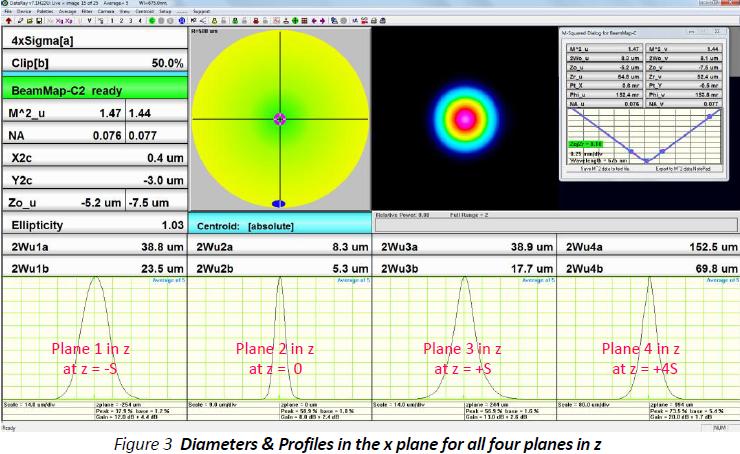
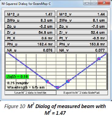
The compact (2.65" x 2.65" x 2.4"), BeamMap2 is the only commercially available multi-plane beam-profiling head. A screenshot of the BeamMap2 in use in DataRay software is shown below. Here you can see four simultaneous beam profiles at four different z locations. The software shows that this beam is focused correctly in X, Y, & Z, and that the M2 of this beam is 1.47.
Measuring & Aligning Tightly Focused Beams
Prior to alignment and focusing, the laser beam …
… may not be focused at z = 0.
… may be misaligned in position and angle.
… may meet neither the beamwaist diameter nor the irradiance specifications.
… may have M2 (Beam Quality) greater than specification.
For an instrument with a single z-plane of measurement, finding the focus is a truly frustrating exercise. Setting multiple production assemblies to the identical focus is time consuming and costly. If the assembly does not adjust correctly, you have no real-time indication of what the problem might be. The BeamMap2 enables you to measure and correct these beam focus and alignment errors to μm accuracy.
If these planes are around the focus position, even when not at the focus, the BeamMap2 can:
● Measure the axial misalignment (pointing).
● Indicate the current focus direction in X, Y & Z.
● Estimate the beamwaist diameter at the focus.
● Estimate M2 and/or beam divergence.
● Do all this in real-time at a 5 Hz update rate.
When the beamwaist is positioned close to the 'zero' measurement plane, these estimates become measurements of:
· Focus position in Z.
· X-Y position and Pointing angle.
· Beam-waist diameter and irradiance.
· M2 Beam Quality and/or beam divergence.
… with sub-micron repeatability,
… with respect to BeamMap2 axes or a user-defined reference.
Measurements using the BeamMap2
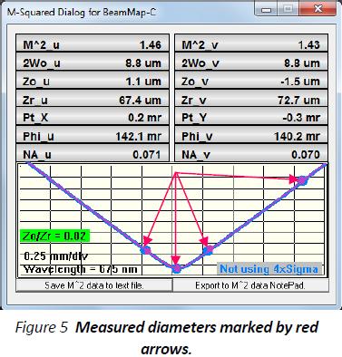
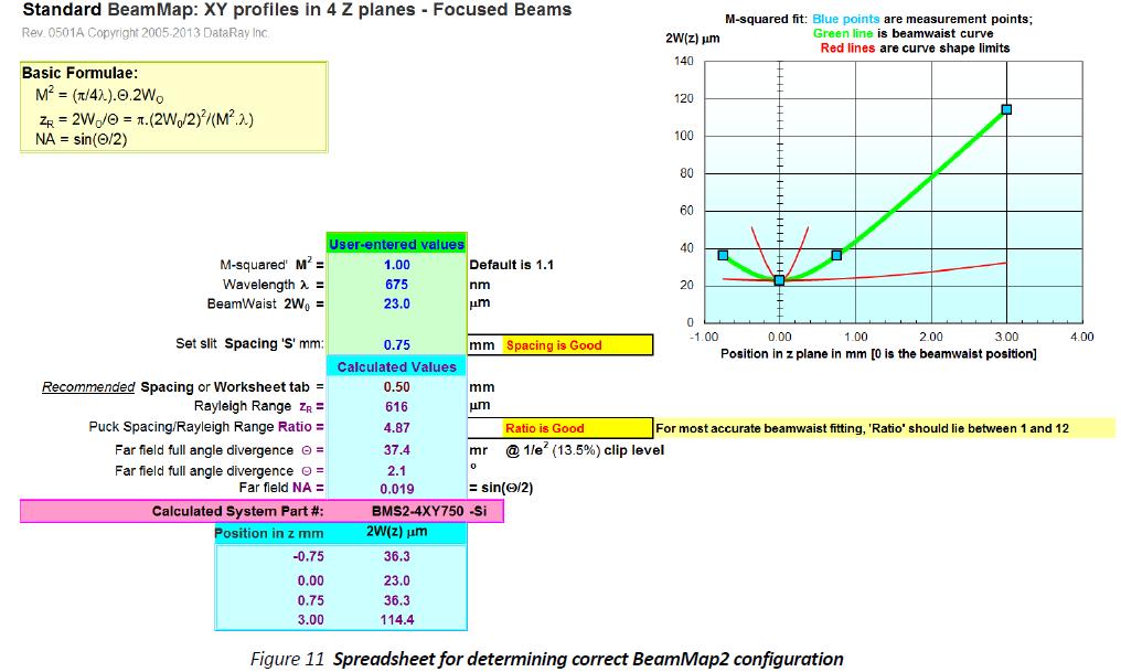
In addition to the display of profiles and diameters, the software does specific calculations, accessed by pressing the M2 button in the toolbar. The software performs a least squares hyperbolic fit to the data.
· The wider blue points and lines are for the u axis (normally x) diameters. The thin purple line is for the v axis (normally y) diameters.
· Horizontal scaling is normalized to the plane separation of the head. Vertical scale is normalized to show the highest measured diameter at ~80%.
· The center of the horizontal plane is the '0' plane of the head.
Results displayed for the two axes are:
M^2 : dimensionless, equals 1.0 for a perfect TEM00 Gaussian beam, >1.0 for imperfect beams and higher order beams.
2Wo: μm, the minimum measured beamwaist diameters.
Zo: μm, the beamwaist z positions relative to the zero plane.
Zr: μm, the beam Rayleigh Range.
Pt: mr, the Pointing Angle with respect to the head, sometimes termed Aiming or Bore-sight.
Phi: mr, the beam far-field Divergence, Φ.
NA: dimensionless, the beam Far-Field Numerical Aperture.
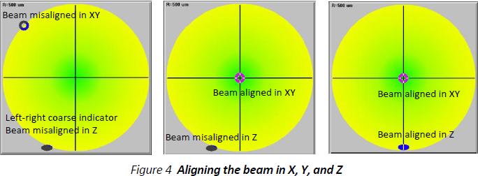
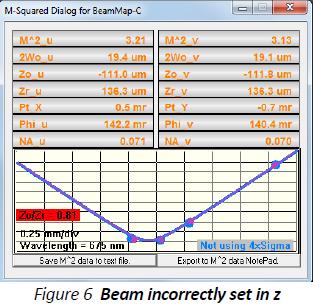
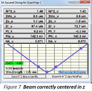
The calculated Zo/Zr, for the u axis only, is displayed in a bar which changes color. For accurate calculations, the beam or instrument position is adjusted in z until the ratio is displayed in green, indicating that Zo/Zr <0.20. (i.e. 2Wo within 2% of its nominal value). It goes yellow, then red for higher ratios. This allows for easy visual confirmation that your beam is focused correctly.
Focus/Beamwaist Alignment & Optimization
The instrument or the beam is moved in z until the beamwaist lies close to the 'zero' plane (indicated when Zo/Zr turns green). This is a very simple procedure. See a video of this in action: Video: Real-time adjustment of a laser assembly beamwaist in Z.
Laser assembly alignment in production
In applications such as laser printing, flow cytometry, optical switching and other laser assemblies, a common use of the BeamMap2 is to achieve significant time and cost savings in the alignment of multiple production assemblies to an identical beamwaist diameter, XYZ position, and Pointing.
The head is first aligned on a reference ('golden') production assembly and the measured values noted. Subsequent heads are aligned and adjusted to give the same focus and desired results. Savable software settings for Production can include Pass/Fail criteria and color coding of the results, plus simpler, less busy, screen displays.
Inaccessible beamwaist? For inaccessible beamwaists such as waveguide facets and lens ended fibers, DataRay offers a LensPlate2™ composed of back to back precision glass aspherics to reimage the waist into the BeamMap2.
Far-field Divergence & Pointing
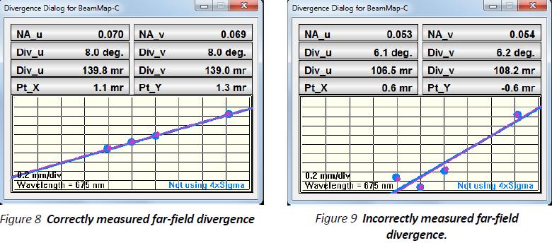
The Divergence function performs a least squares straight line fit to the beam diameter and centroid values versus measurement plane, determining the angular Divergence and the Pointing of the beam (also termed Aiming or Bore-sight). This unweighted fit assumes a straight-line divergence, generally applicable in the far field more than about three Rayleigh Ranges from the focus.
Results are displayed in terms of Numerical Aperture and full angle Divergence in degrees and mr. The measurement will be incorrect if it is made too close to the focus.
M2 Beam Quality & Divergence
The BeamMap2 may be configured to measure M2 in real-time. The 5 Hz update rate allows for real-time alignment and adjustment of beams to meet specific M2 criteria. The BeamMap2 meets the technical requirement for M2 measurement, which is accurate measurement of the beamwaist diameter and of the far field divergence. In particular, the BeamMap2 can give an excellent feel for relative M2 between different laser assemblies.
In practice, the beam or the instrument head is adjusted in z until Zo/Zr is green. The fitted hyperbolic curve is based on the measured 2Wo beam diameter in the zero plane and the other three diameter measurements.
Zo, Zr, Phi & NA are derived from the hyperbolic fit. M2 is derived from 2Wo and Phi. The values are presented in real time.
BeamMap2 Configurations, Selection & Technology
BeamMap2 heads are configured to suit the beam diameters and wavelengths to be addressed:
● Primary plane spacing, S, available at 50, 100, 250, 500 or 750 μm.
● 5 mm plane spacing BeamMap2 ColliMate variant for beams with beamwaists of a few hundred μm.
● Silicon, InGaAs or extended InGaAs detectors, UV to 2500 nm.
● 2.5 or 5.0 μm width True 2D™ slit pairs, plus 25 or 50 μm if KE mode is required. See Appendix A.
DataRay can specify the appropriate head by running a simple Excel spreadsheet (example below) based upon your range of beamwaists and wavelengths.
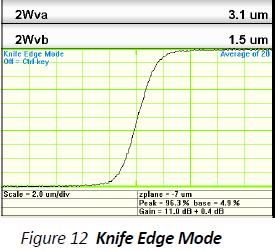
Knife Edge (KE) Mode for very small beams
Specific BeamMap2 configurations for very small beams (few microns) can include wide slit pairs which support KE mode. When the beam diameter is much smaller than the width of the wide slit, the software automatically displays & analyses the integral power curve from the leading edge of the slit. Displayed 2W values assume that the beam is Gaussian, generally true for very small beams.
BeamMap2 Software Interfacing
Many results are exportable to Excel, to text files, to Paint, and to the clipboard.
DataRay actively supports BeamMap2 operation from other software. Specific documentation & sample code is available for Active X interfacing to:
·Visual Studio C + +
·Labview
·Visual Basic
Find out more at our software support page.
Multi-plane Beam Profiling Speeds Development & Production
nce you see a BeamMap2 in action, you'll never want to use a conventional single plane beam profiler again. The unique, patented BeamMap2 simplifies typical laser assembly alignment. Add a BeamMap2 to your assembly and in no time, you'll have real-time guidance on beam focus and alignment. Prior to exact focusing, the BeamMap2 will measure beam pointing, indicate the current focus direction, estimate the beamwaist diameter, and estimate the M2 and/or beam divergence in real-time. The system then guides you in focusing the beam to exactly where it needs to be with real-time images and color-coded feedback (keep adjusting until you see green). At this point in time, all of the estimates will become accurate measurements.
Whatever your beam needs are, even for few m diameter beams, there is a BeamMap2 configuration available for you. Silicon, InGaAs, and extended InGaAs detectors cover UV to 2500 nm.
Use our intuitive software or incorporate our device into your own test software environment.
The BeamMap2 will dramatically speed up the real-time diagnosis of focusing and alignment errors and the setting of multiple assemblies to the same focus.
See our website www.dataray.com or contact sales@dataray.com for more information.
Appendix A: True-2D™ slits
DataRay developed specific optimized slits for use on the small beams with low Rayleigh ranges that the BeamMap2 can measure. Conventional 'air' slits in standard slit scanners are 12.5 or 25 ?m thick in the z direction, or 6 ?m thick for the best available. To a tightly focused beam, they look like a partially reflective tunnel rather than a two-dimensional slit. This reduces the accuracy of the focus determination.
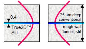
True2D™ slits are photo-lithographically defined in multiple opaque layers deposited on semiconductor grade, polished sapphire substrates. Total layer thickness is ~0.4 microns, an order of magnitude thinner than the best air slits. The thermally conductive sapphire substrate supports high irradiance performance and accurate profiling of very tightly focused beams.